
What do you need?
Niko requirements
Your Niko Home Control installation meets the following requirements:
-
It has a wireless smart hub or a connected controller II.
-
It is configured with the most recent programming software.
Depending on the basic modules of your Niko Home Control installation, you need to install the following additional products:
|
|
Required additional products |
Reference numbers |
|---|---|---|
|
Connected controller |
Digital potential-free sensor module with one free input per signal that you want to use in Niko Home Control If the output contact on your third-party device is not potential-free, you need an additional potential-free contact module (e.g. Finder 22.32.0.230.1xx0 for 230 V connections, Finder 22.32.0.012.1xx0 for 12 V DC connections, Finder 22.32.0.024.1xx0 for 24 V DC connections) |
|
|
Connected controller with a wireless bridge |
Connected (double) switch with one free input (E) per signal that you want to use in Niko Home Control If the output contact on your third-party device is not 230 V, you need an additional 230 V contact module (e.g. Finder 22.32.0.230.1xx0 for potential-free connections, Finder 22.32.0.012.1xx0 for 12 V DC connections, Finder 22.32.0.024.1xx0 for 24 V DC connections) The connected (double) switch can be placed on a DIN rail using a modular holder (e.g. Legrand 412950) |
|
|
Wireless smart hub |
Connected (double) switch with one free input (E) per signal that you want to use in Niko Home Control If the output contact on your third-party device is not 230 V, you need an additional 230 V contact module (e.g. Finder 22.32.0.230.1xx0 for potential-free connections, Finder 22.32.0.012.1xx0 for 12 V DC connections, Finder 22.32.0.024.1xx0 for 24 V DC connections) The connected (double) switch can be placed on a DIN rail using a modular holder (e.g. Legrand 412950) |
Third party system requirements
Your system meets the following requirements:
-
Your alarm system has potential free or 12/24 V DC 230 V AC output contacts that signal when the alarm system is (dis)armed.
-
It is compatible with the Niko module (see Niko requirements).
Wiring diagrams
If you also want to receive a signal when the alarm goes off, you need to connect an additional contact, see General solution: Security alarm notification.
Connecting the sensor module
Via potential-free output contact
Connect contact 1 on the Niko sensor module to the output on the third-party system, as shown in the wiring diagram.

Via 230 V or 12/24 V output contact
If the contacts of your alarm system are not potential-free, you additionally need an appropriate potential-free contact module.
Connect contact 1 on the Niko sensor module to the output on the third-party system, as shown in the wiring diagram.
|
230 V output contact |
12/24 V output contact |
|---|---|

*230 V to potential-free contact module (e.g. Finder 22.32.0.230.1xx0) |
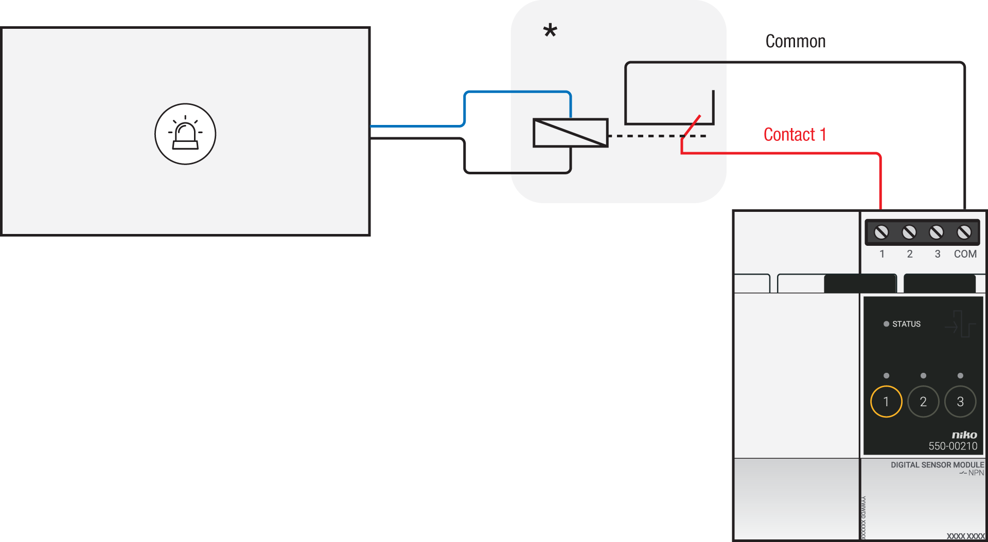
*12 V to potential-free contact module (e.g. Finder 22.32.0.012.1xx0) or 24 V to potential-free contact module (e.g. Finder 22.32.0.024.1xx0) |
Connecting the connected switch
Via potential-free output contact
If the contacts of your alarm system are not 230 V, you additionally need an appropriate potential-free contact module.
Connect contact 1 on the Niko connected switch to the output on the third-party system, as shown in the wiring diagram.

*230 V to potential-free contact module (e.g. Finder 22.32.0.230.1xx0)
Via 230 V or 12/24 V output contact
If the contacts of your alarm system are not 230 V, you additionally need an appropriate contact module.
Connect contact 1 on the Niko connected switch to the output on the third-party system, as shown in the wiring diagram.
|
230 V output contact |
12/24 V output contact |
|---|---|
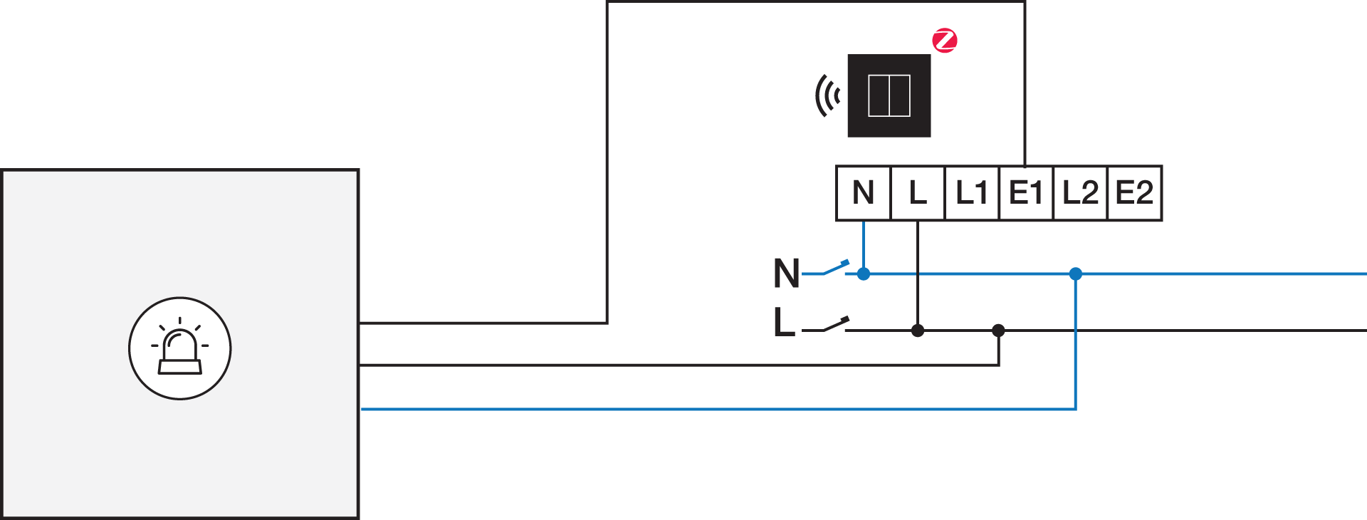
|
*12 V to 230 V contact module (e.g. Finder 22.32.0.012.1xx0) or 24 V to 230 V contact module (e.g. Finder 22.32.0.024.1xx0) |
Programming
Configure the potential-free sensor module or connected switch and create conditions and/or routines via the Niko Home Control programming software. You can use the following programming examples as inspiration or as a starting point: