Description
Overview
Description
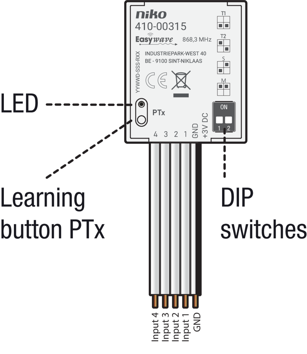
With this built-in transmitter, the functionality of existing switches or buttons can be extended with a radio interface.
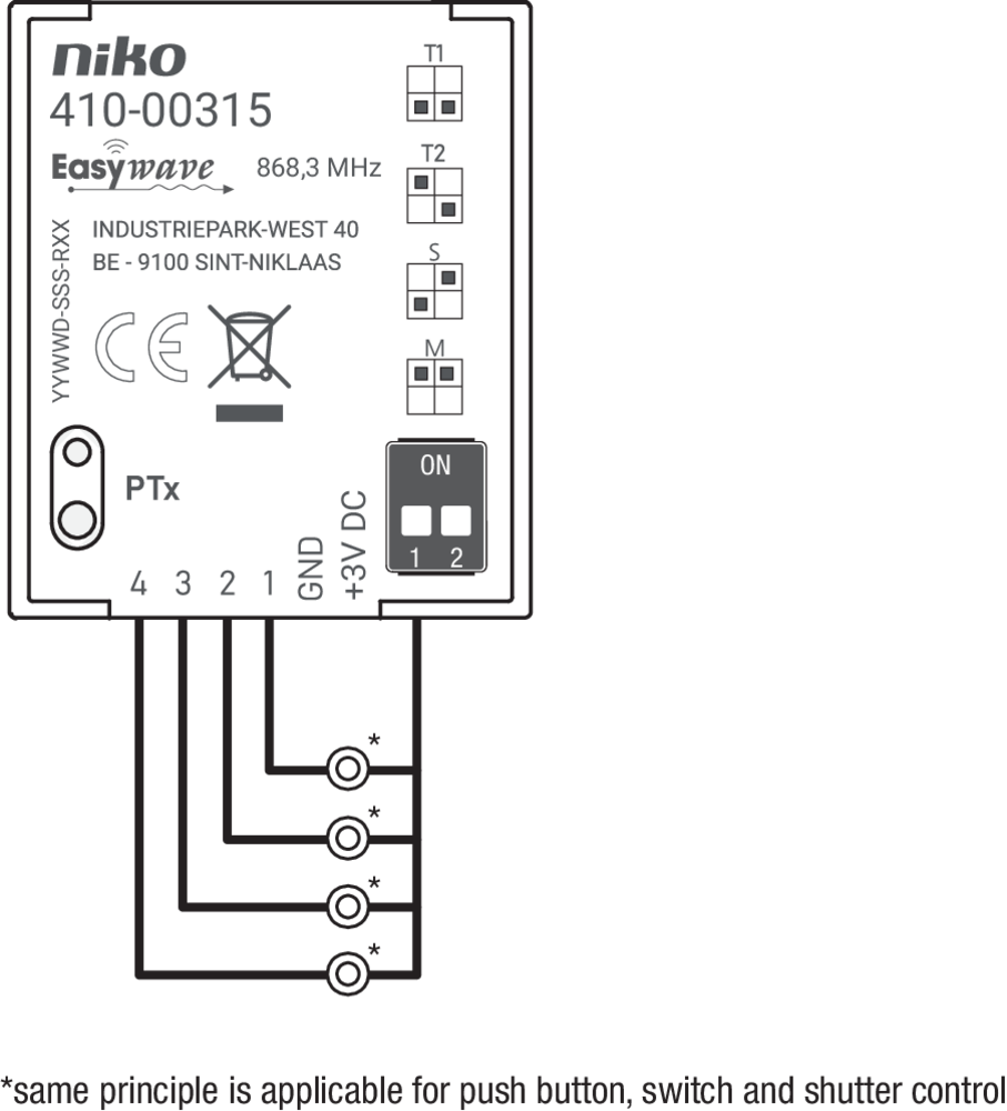
When one of the four inputs (1, 2, 3, 4) is switched potential-free to GND, the transmitter sends a corresponding Easywave code. Which transmission code is sent, depends on the operating mode set via the DIP switches.
The learning button is used to pair (teach-in) the transmitter to an RF receiver (410-0033x).
You can connect buttons, switches and interlocked shutter switches. The LED lights up red during the transmission process.
Operation and use
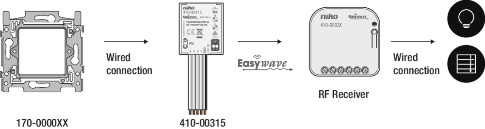
The diagram below shows the operational principle:
-
A push button or switch (170-0000xx) is hardwired to the transmitter.
-
When the button is pressed, the transmitter sends a wireless (Easywave) signal.
-
That signal is picked up by an RF receiver (410-0033x).
-
The receiver is hardwired to the device to be activated (e.g. light).
-
The receiver activates the device.
Compatible products
-
This product is compatible with Niko Flush-mounting RF receivers (410-0033X).
-
This product can be installed behind a Niko blind plate (XXX-76900) or external wired push button (e.g. 170-0000X) in the colour of your choice.
-
This product is compatible with the Niko wireless Smart Hub (552-00002).
-
Mini RF Interface (05-315)
-
In combination with the Niko Home Control USB RF interface (410-00099), the hand-held transmitter can also be used in Niko Home Control bus installations.
Power supply
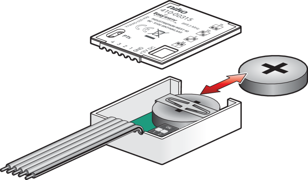
Replacing the battery
230 V – OFF
-
Open the lid of the casing and remove the old battery (if present).
-
Insert a new battery. Use only batteries of type CR2032.
-
Close the lid of the casing.
Alternatively (and optionally), you can connect an external power supply.
Connecting an external power supply (optional)
230 V – OFF
Before you start, prepare the 3VDC wire:
-
Use a 0.5mm² LYI stranded wire, and strip approximately 2.5 mm of insulation
-
Tin the end.
-
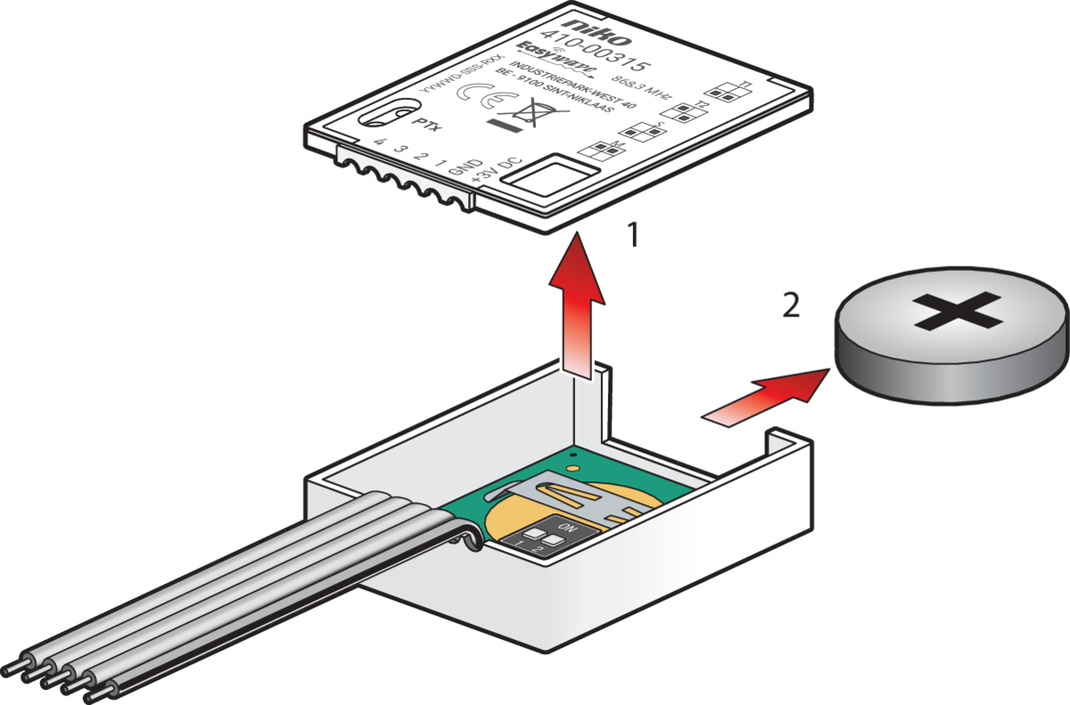
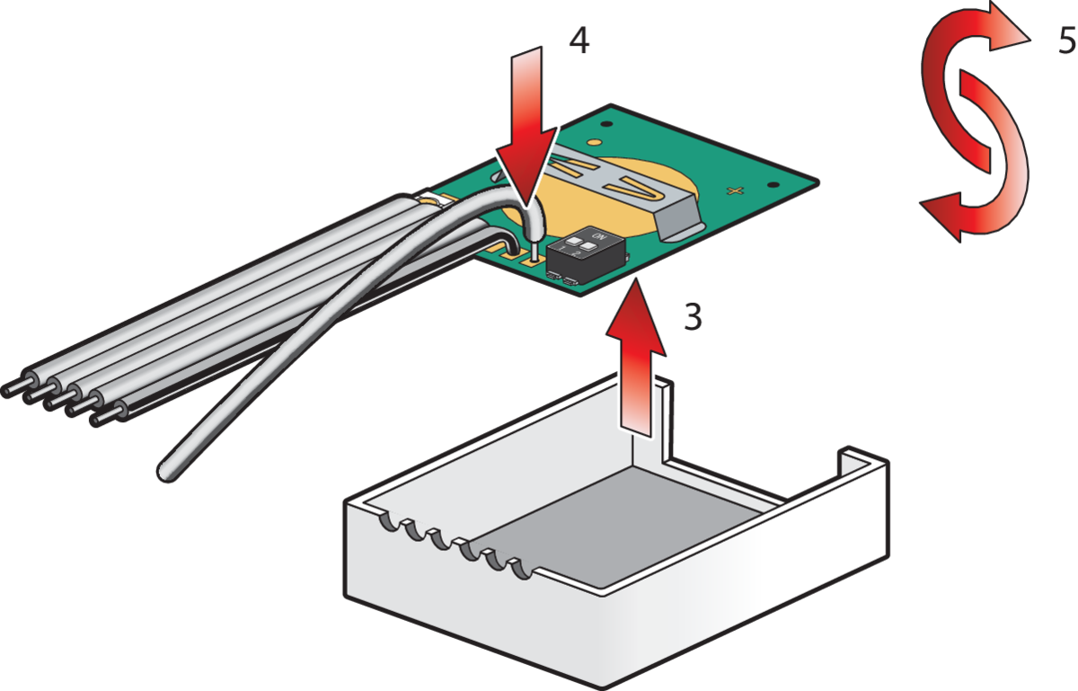
Open the lid of the casing.
-
Remove the battery (if present).
-
Remove the PCB from the casing.
-
Insert the tinned end of the 3VDC wire into the hole provided on the board.
-
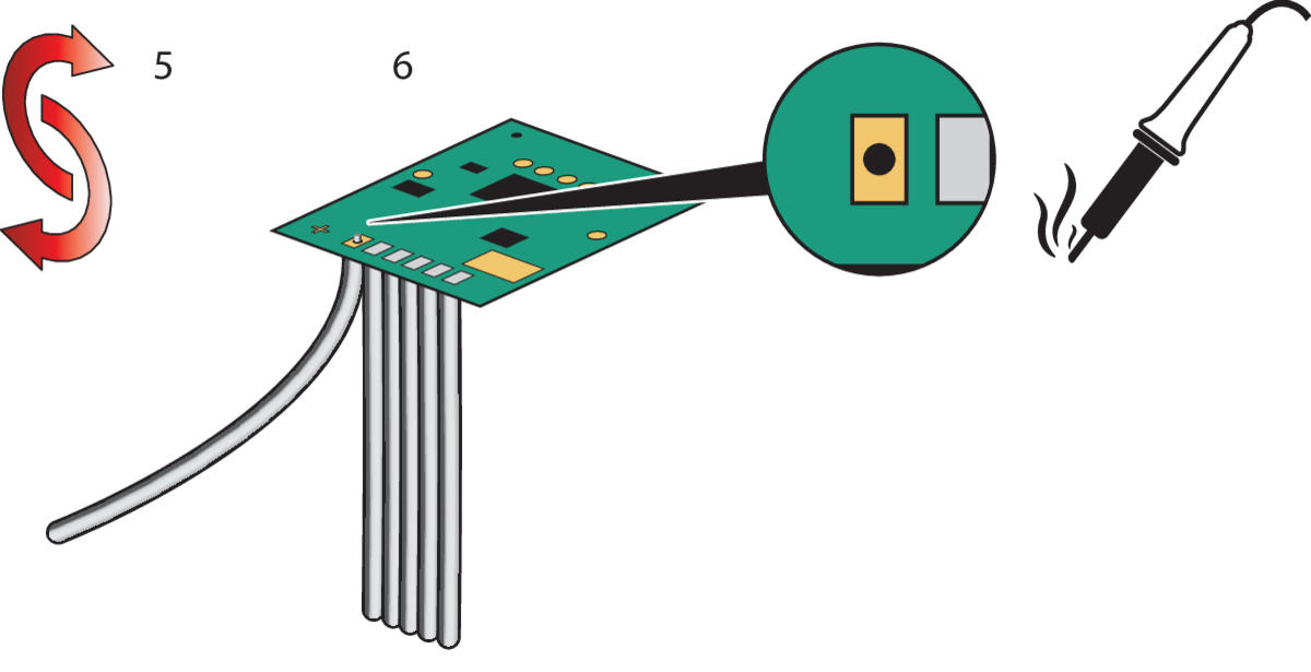
Turn over the PCB .
-
Solder the wire to the PCB.
-
Correctly insert the PCB into the casing and close the lid.
-
Use a 3V external power supply. Never connect the transmitter to the 230V power supply.
Installation
Installation instructions
230 V – OFF
-
Open the housing
-
Set the desired operating mode using the DIP switches.
-
Connect the buttons or switches to terminals 1-4 and GND according to the wiring diagram.
-
Install the battery and/or connect the external power supply.
-
Close the housing
-
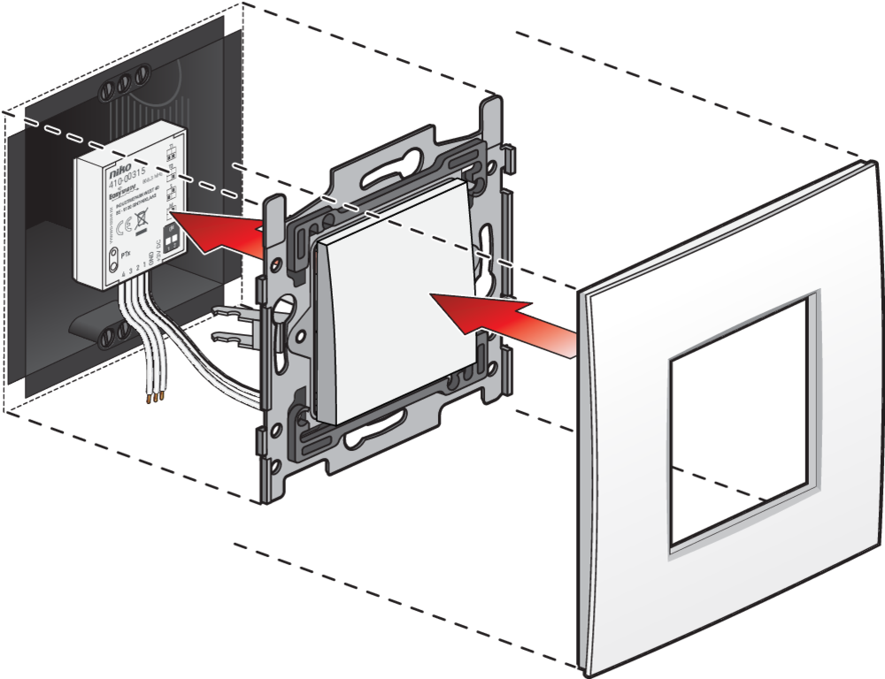
Place the transmitter in the mounting box
Mounting tips
You can mount the transmitter behind an externally wired push button:
Mount the transmitter at a suitable location. Avoid mounting at the following locations, as this may affect the range of the transmitter:
-
in a distribution box or housing made of metal
-
in the immediate vicinity of large metal objects
-
on the ground (or near it).
Wiring
The wiring diagram is shown below:
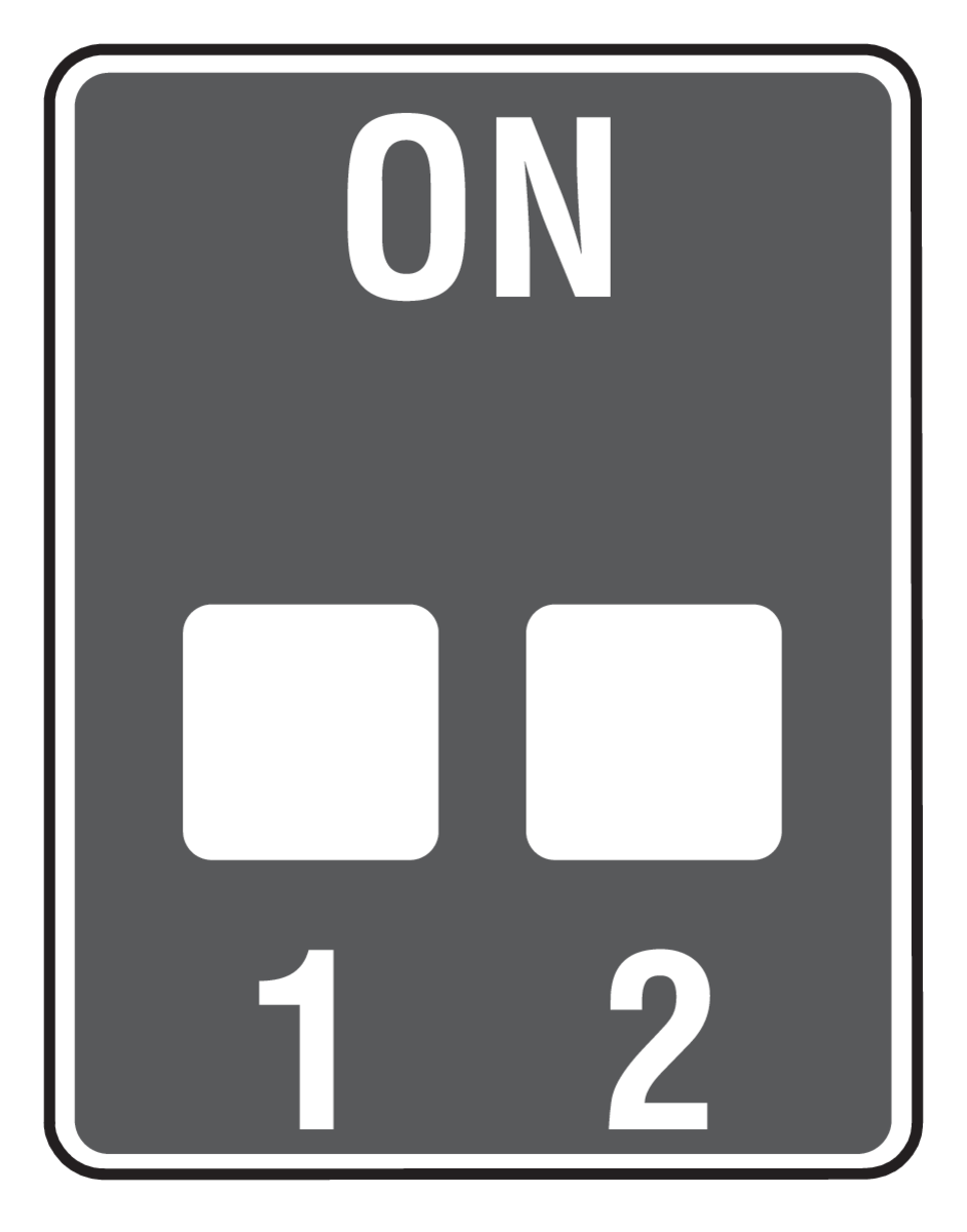
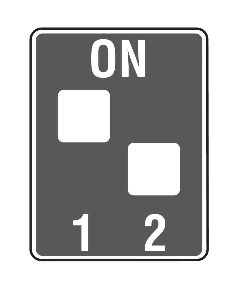
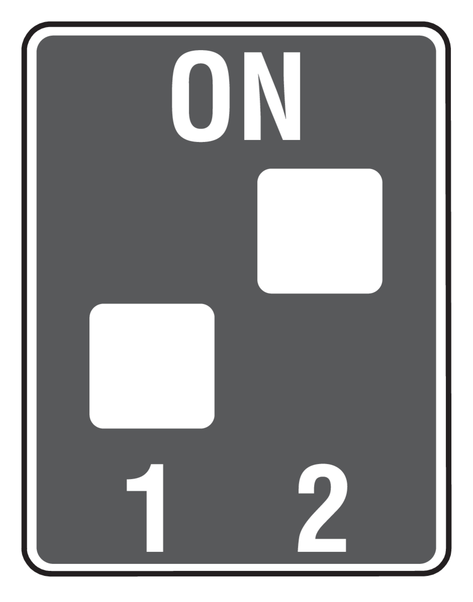
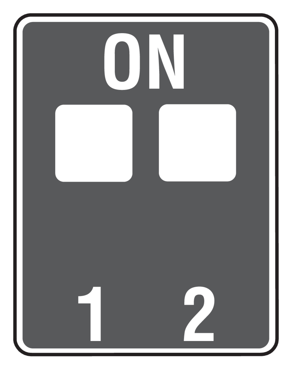
Setting the operation modes
Use the DIP switches to set the operation mode.
To apply changes to the operation mode, restart the transmitter. After making changes with the battery or external power connected, briefly cut power by removing the battery or disconnecting the external supply.
|
Mode |
Details |
DIP switch setting |
|---|---|---|
|
Push button 10s (T1) |
max. 10 seconds transmission time
|
|
|
Push button 36s (T2) |
max. 36 seconds transmission time
|
|
|
Switch (S) |
Suitable receiver operating modes:
|
|
|
Shutter control (M) |
Suitable receiver operating modes:
|
|
Product Information
Technical details
-
Frequency: 868.30 MHz
-
Radiated power: 0.47 mW
-
Modulation: FSK
-
Coding: Easywave
-
Power consumption: 1x 3V-battery CR2032 OR 3V DC wired
-
Transmit current: approx. 12 mA
-
Stand-by current: approx. 2.5 μA
-
Range: free-field: approx. 150 m - buildings: approx. 30 m
-
Operating temperature: -20 °C to +60 °C
-
Dimensions (W/L/H): 29,2/34,7/9,0 mm
-
Weight: 12.0 g
Scope of delivery
-
Built-in transmitter, battery CR2032,
-
Operating instructions
Disclaimer
Read the manual completely before installing and activating the system.
Niko prepares its manuals with the greatest care and strives to make them as complete, correct and up to date as possible. Nevertheless, some deficiencies may subsist. Niko cannot be held responsible for this, other than within the legal limits. Please inform us of any deficiencies in the manuals by contacting Niko customer services at support@niko.eu.
Legal Information
nv Niko sa
Industriepark West 40
9100 Sint-Niklaas, Belgium
+32 3 778 90 80
support@niko.eu
Warnings regarding installation

|
The installation of products that will permanently be part of the electrical installation and which include dangerous voltages, should be carried out by a qualified installer and in accordance with the applicable regulations. This user manual must be presented to the user. It should be included in the electrical installation file and it should be passed on to any new owners. Additional copies are available on the Niko website or via Niko customer services. |
CE Marking

|
This product complies with all of the relevant European guidelines and regulations. For radio equipment Niko llc declares that the radio equipment in this manual conforms with the 2014/53/EU directive. The full text of the EU declaration of conformity is available at https://www.niko.eu under the product reference, if applicable. |
Environment

|
This product and/or the batteries provided cannot be disposed of in non-recyclable waste. Take your discarded product to a recognised collection point. Just like producers and importers, you too play an important role in the promotion of sorting, recycling and reuse of discarded electrical and electronic equipment. To finance the rubbish collection and waste treatment, the government levies recycling charges in certain cases (included in the price of this product). |