What do you need?
Niko requirements
Din Niko Home Control-installation uppfyller följande krav:
-
Den har en trådlös gateway eller en ansluten kontrollenhet II
-
Den är konfigurerad med den senaste programmeringsprogramvaran.
Beroende på vilka grundläggande moduler din Niko Home Control-installation har behöver du installera följande extraprodukter:
|
|
Nödvändiga extraprodukter |
Referensnummer |
|---|---|---|
|
Ansluten kontrollenhet |
Digital potentialfri sensormodul med en ledig ingång per signal som du vill använda i Niko Home Control Om utgångskontakten på din tredjepartsenhet inte är potentialfri behöver du lägga till en potentialfri kontaktmodul (t.ex. Finder 22.32.0.230.1xx0 för 230 V-anslutningar, Finder 22.32.0.012.1xx0 för 12 V DC-anslutningar, Finder 22.32.0.024.1xx0 för 24 V DC-anslutningar) |
|
|
Ansluten kontrollenhet med en trådlös brygga |
Smart (dubbel) strömställare med en ledig ingång (E) per signal som du vill använda i Niko Home Control Om utgångskontakten på din tredjepartsenhet inte är 230 V behöver du lägga till en 230 V-kontaktmodul (t.ex. Finder 22.32.0.230.1xx0 för potentialfria anslutningar, Finder 22.32.0.012.1xx0 för 12 V DC-anslutningar, Finder 22.32.0.024.1xx0 för 24 V DC-anslutningar) Den smarta (dubbla) strömställaren kan placeras på en DIN-skena med en modulär hållare (t.ex. Legrand 412950) |
|
|
Trådlös gateway |
Smart (dubbel) strömställare med en ledig ingång (E) per signal som du vill använda i Niko Home Control Om utgångskontakten på din tredjepartsenhet inte är 230 V behöver du lägga till en 230 V-kontaktmodul (t.ex. Finder 22.32.0.230.1xx0 för potentialfria anslutningar, Finder 22.32.0.012.1xx0 för 12 V DC-anslutningar, Finder 22.32.0.024.1xx0 för 24 V DC-anslutningar) Den smarta (dubbla) strömställaren kan placeras på en DIN-skena med en modulär hållare (t.ex. Legrand 412950) |
Third party system requirements
Ditt system uppfyller följande krav:
-
Din sensor för vattenläckor har en potentialfri eller 12/24 V DC eller 230 V AC utgångskontakt.
-
Det är kompatibelt med Niko-modulen (se Niko-krav).
Wiring diagrams
Connecting the sensor module
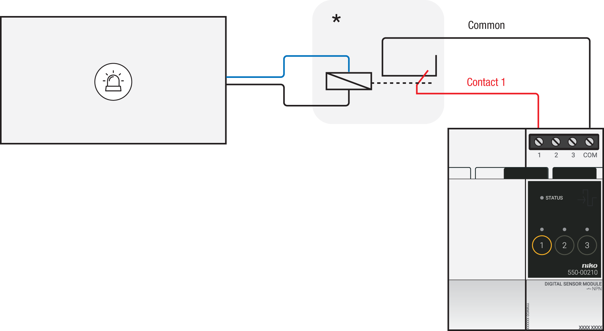
Via potential-free output contact
Connect contact 1 on the Niko sensor module to the output on the third-party system, as shown in the wiring diagram.

Via 230 V or 12/24 V output contact
If the contacts of your alarm system are not potential-free, you additionally need an appropriate potential-free contact module.
Connect contact 1 on the Niko sensor module to the output on the third-party system, as shown in the wiring diagram.
|
230 V output contact |
12/24 V output contact |
|---|---|
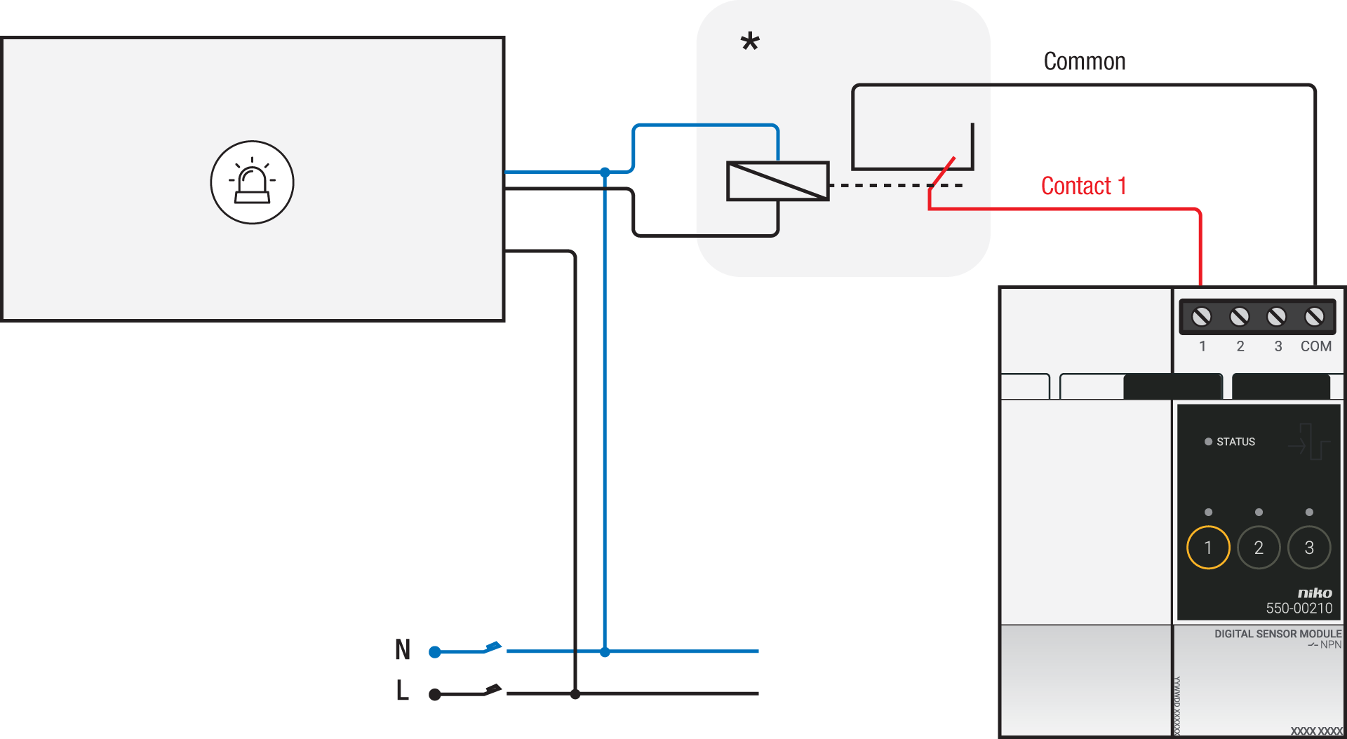
*230 V to potential-free contact module (e.g. Finder 22.32.0.230.1xx0) |
*12 V to potential-free contact module (e.g. Finder 22.32.0.012.1xx0) or 24 V to potential-free contact module (e.g. Finder 22.32.0.024.1xx0) |
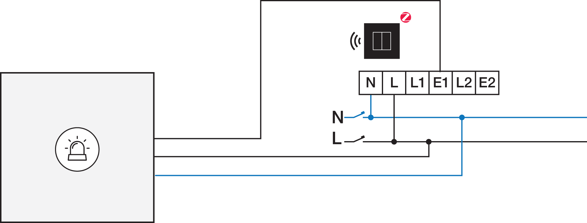
Connecting the connected switch
Via potential-free output contact
If the contacts of your alarm system are not 230 V, you additionally need an appropriate potential-free contact module.
Connect contact 1 on the Niko connected switch to the output on the third-party system, as shown in the wiring diagram.

*230 V to potential-free contact module (e.g. Finder 22.32.0.230.1xx0)
Via 230 V or 12/24 V output contact
If the contacts of your alarm system are not 230 V, you additionally need an appropriate contact module.
Connect contact 1 on the Niko connected switch to the output on the third-party system, as shown in the wiring diagram.
|
230 V output contact |
12/24 V output contact |
|---|---|
|
*12 V to 230 V contact module (e.g. Finder 22.32.0.012.1xx0) or 24 V to 230 V contact module (e.g. Finder 22.32.0.024.1xx0) |