
Product information
Applicable products
This guide is applicable to the following products:
-
552-42102 | MOTIV Wireless relay 4A / 2x
-
552-42401 | MOTIV Wireless potential-free contact
-
552-42301 | MOTIV Wireless motor control 2A
-
552-42201 | MOTIV Wireless LED dimmer 200W
These links direct you to the product pages. There, you will find detailed specifications, certificates of CE-marking, etc.
Compatibility
These products are compatible with:
-
Niko Home Control II (Niko Home Control wireless network (2.4 GHz))
-
MOTIV Wireless
when using a wireless bridge or a wireless smart hub.
Control
Signal range
Typical range
The typical point-to-point indoor range is ± 10 m. The meshing capability of 230 V powered wireless mesh devices can extend the RF range.
For more information about mesh networks, see https://guide.niko.eu/en/hmnhc2/lv/Mesh-network-principle
Materials and obstructions
Radio waves can be attenuated by materials inside a building or room. The maximum point-to-point RF range of the connected switch to a wireless receiver depends on:
-
The materials used in the building or room,
-
The indoor position of the connected switch and
-
Sources of interference.
The table below provides an overview of common materials and corresponding losses:
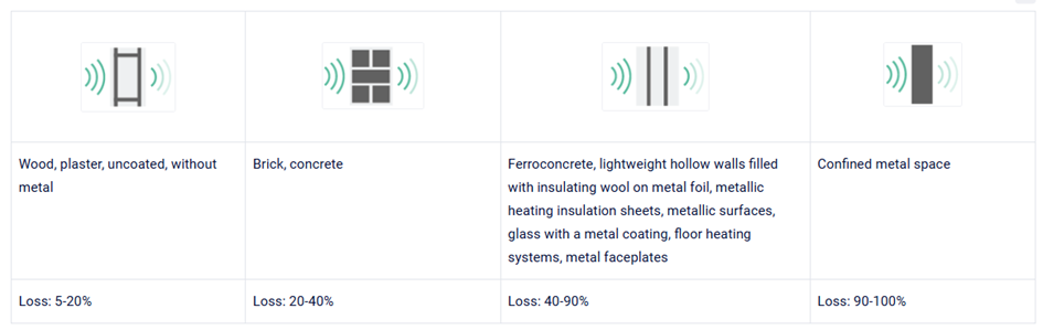
The human body can obstruct RF signal propagation because the 2.4 GHz frequency band is strongly attenuated by water-rich materials. While the wireless network's mesh functionality generally maintains connectivity despite partial signal obstruction, installations in environments with large numbers of people or objects containing substantial amounts of water (such as aquariums) should be carefully evaluated, as these can reduce signal strength and degrade overall RF performance.
Installation position
To ensure reliable wireless communication, avoid installing the wireless module in the following locations:
-
In narrow rooms with thick walls.
-
On the same wall as another wireless repeater or receiving module.
-
Less than 110 cm above floor level (recommended mounting height: 110 cm).
-
On metal surfaces, damp surfaces, or areas with high humidity.
-
In RF "dead spots" caused by signal reflections or attenuation from nearby conductive materials or obstacles, such as metal cabinets, doors containing metallic foil, or objects with a high water content (for example, aquariums).
Maintain a minimum separation distance of 2 m between any wireless module (including the Smart Hub) and other RF transmitters, such as Wi-Fi access points or routers. The same minimum distance should be maintained from equipment that may generate electromagnetic interference (EMI), including electric motors, pumps, electronic LED drivers, solar inverters, and residential battery energy storage systems.
Sources of interference
Wireless modules are generally immune to interference from low-power electronic devices, including DECT telephones, smartphones, Wi-Fi access points and routers, analogue radios, electronic ballasts, control equipment, televisions, audio/video equipment, computers, and remote controls.
The wireless network uses a robust RF communication protocol with self-healing mesh functionality, enabling reliable communication even in environments with moderate levels of electrical noise. However, high-power electrical or electronic equipment may occasionally degrade RF performance. If interference is suspected, identify and eliminate the source where possible. Where this is not practical, improve network coverage by relocating the wireless module or installing an additional repeater node, such as a compatible mains-powered (230 V AC) wireless module.
Wiring Scheme, LEDs and Push-buttons
Click below for more information:
Installing the connected switches
Prerequisite: Prior to installing the wireless module, install a flush-mounting box and the required electrical wiring.
230 V OFF
Step 1 - Connecting
Connect the supply voltage and the devices to be controlled, according to the wiring diagram.
Use wires with a cross-sectional area of 0.5 mm² to 2.5 mm² only. Strip the insulation from each conductor by 6 to 7 mm before connection.
Step 2 - Addressing
230 V ON
The push-buttons and LED on module must remain accessible during the configuration.
Onboard and configure the wireless module using the Niko Home Control programming software. Add, configure, and assign the wireless modules in accordance with the standard workflow and configuration procedures defined within the software. For more details, see:
Addressing flow
-
Select the wireless device to be addressed in the programming software.
-
Start the addressing procedure using one of the following methods:
-
Method 1: If the device has not yet been connected to a network, it automatically enters network pairing mode when powered on. The pairing mode remains active for 180 seconds.
-
Method 2: Press the Reset/K1 button briefly five times.
-
During addressing mode, the LED flashes rapidly. Once the addressing process is successfully completed, the LED switches off.
Troubleshooting and maintenance
Troubleshooting
|
Problem |
Cause |
Action |
|
My smart hub or wireless bridge doesn't work anymore |
Consult the manuals of the wireless smart hub (552-0000x) or the wireless bridge (550-00640) for more information on the possible cause |
If the power of the smart hub or wireless bridge switches off, all 230 V connected devices will continue to operate in stand-alone mode via their own local contact (if wired). |
|
The module is in overload |
The connected load is too high |
Check load consumption Power cycle module to recover from overload status. |
|
The module cannot be found in the programming software, or it cannot be paired into the network |
The power supply is off |
Switch on the power supply |
|
The wireless device is still connected to another network |
Factory reset the device according to the instructions of the manual. |
|
|
The wireless device and the smart hub or wireless bridge are located too close |
Make sure there is a distance of at least 2 metres between the wireless device and the smart hub or wireless bridge for Niko Home Control. The same minimum distance must be respected between the Wi-Fi router and the smart hub or wireless bridge |
|
|
The wireless device and the smart hub, wireless bridge or another connected device are separated too far from each other |
Make sure there is a maximum of 10 metres between the wireless device and the smart hub, wireless bridge or a subsequent 230 V wireless device. To increase the range, you can for example add an additional 230 V powered wireless device to the network |
|
|
There is no connection between the laptop/pc with the programming software and the smart hub or wireless bridge |
Check the connection to the smart hub or wireless bridge. |
|
|
Consult the respective product manuals to resolve this issue |
||
|
Other cause: all the above causes and corresponding actions have been tried but didn't solve the problem |
Enter the MAC address and installation code manually. If the problem persists after uploading the configuration, please contact Niko customer services. |
|
|
The load does not switch on |
The miniature circuit breaker (MCB) of the circuit is disabled or there is a short circuit |
Check whether the load complies with the load specifications described in the manual |
|
The switch is defective |
Power down the smart hub or the wireless bridge to bring the connected switch into stand-alone mode. Press the switch button so that you can hear the in-built relay switch. Replace the product if you cannot hear the relay |
|
|
Wiring is disconnected |
Check wiring and reconnect it. |
|
|
The load is defective |
Connect a lamp to the connected switch of which you are 100% sure it works. If this lamp lights up, the previous one was faulty |
Wireless network reset
When the reset command is executed, only active wireless devices receive the command. These devices leave the network, and their internal network configuration data is cleared, allowing them to be added to another wireless network without requiring a manual factory reset.
Active devices typically include 230 V-powered wireless modules, which continuously monitor the wireless network. Battery-powered devices are only active during operation and for approximately 90 seconds afterward.
Inactive wireless devices do not receive the reset command. These devices must be manually factory reset before they can be added to a different wireless network.
The reset function clears the complete wireless network configuration, including the network channel and network ID stored in all active wireless devices.
Wireless Device Firmware Upgrade Procedure
When a firmware upgrade is available, a notification is displayed in the latest version of the Niko Home Control programming software or the Niko Home app.
Over-the-Air (OTA) upgrades are not indicated by the device feedback LEDs. However, if the wireless connection is interrupted during the upgrade process, the LED status may change to indicate the communication issue.
All wireless devices are upgraded automatically in sequence. The upgrade process starts within a maximum of 6 hours after the smart hub or connected controller has been updated.
If an upgrade fails, a notification is displayed in the Niko Home Control programming software or the Niko Home app. The wireless device remains operational and continues to use the previously installed firmware version.
For wireless devices used in systems without a Niko Home Control connection, firmware upgrades can be performed manually using the available OTA firmware files at https://download.nikogroup.eu/nhc2/release/upgrades/ota/index.json
Manual network reset
Method 1 - Using the K1 button
Proceed as follows:
-
Press the K1 button briefly five times to perform a factory reset and initiate network pairing mode.
-
After the factory reset, the device enters network pairing mode. The pairing window remains active for 180 seconds or until the device is successfully added to a new wireless network.
-
Verify the LED status:
-
The LED flashes rapidly after the factory reset, indicating that the device is in pairing mode.
-
If a wireless network is detected, the red LED flashes slowly twice, followed by 180 seconds of rapid flashing while the device searches for a network connection.
-
Once the network is open and pairing is successful, the red LED remains on for 3 seconds and then switches off.
-
The device is now reset and successfully connected to the wireless network.
Method 2 - Using power reset
Proceed as follows:
-
Reset the power of the device 5 times as indicated in the diagram below:

-
Observe the LED status during network pairing:
-
The red LED flashes slowly twice when a nearby wireless network is detected.
-
The LED then flashes rapidly for up to 180 seconds while the device attempts to join the network.
-
-
When the network accepts the device and pairing is successful:
-
The red LED remains continuously illuminated for 3 seconds.
-
The LED then switches off to indicate that the pairing process has been completed.
-
Legal information
Support & Contact
nv Niko sa
Industriepark West 409100 Sint-Niklaas, Belgium
+32 3 778 90 80
Installation warning
The installation of products that will permanently be part of the electrical installation and which include dangerous voltages, should be carried out by a qualified installer and in accordance with the applicable regulations. This user manual must be presented to the user. It should be included in the electrical installation file, and it should be passed on to any new owners. Additional copies are available on the Niko website or via Niko customer services.
CE Marking
This product complies with all of the relevant European guidelines and regulations. For radio equipment Niko LLC declares that the radio equipment in this manual conforms with the 2014/53/EU directive. The full text of the EU declaration of conformity is available at https://www.niko.eu under the product reference, if applicable.
Environmental
This product and/or the batteries provided cannot be disposed of in non-recyclable waste. Take your discarded product to a recognised collection point. Just like producers and importers, you too play an important role in the promotion of sorting, recycling and reuse of discarded electrical and electronic equipment. To finance the rubbish collection and waste treatment, the government levies recycling charges in certain cases (included in the price of this product).
Disclaimer
Carefully read the entire manual before installing and activating the system.
Niko prepares its manuals with the greatest care and strives to make them as complete, correct and up to date as possible. Nevertheless, some deficiencies may subsist. Niko cannot be held responsible for this, other than within the legal limits. Please inform us of any deficiencies in the manuals by contacting Niko customer services at support@niko.eu