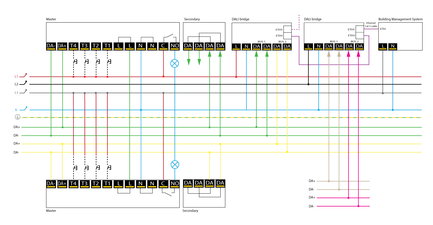
Bridge wiring diagram
Wire the DALI bridge as follows:
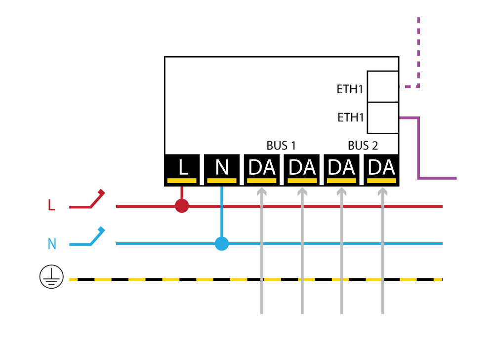
This product must be secured with a miniature circuit breaker of max. 16A in the electrical cabinet. The MCB rating is limited by national installation rules.
Basic wiring configuration
The basic configuration is as follows:
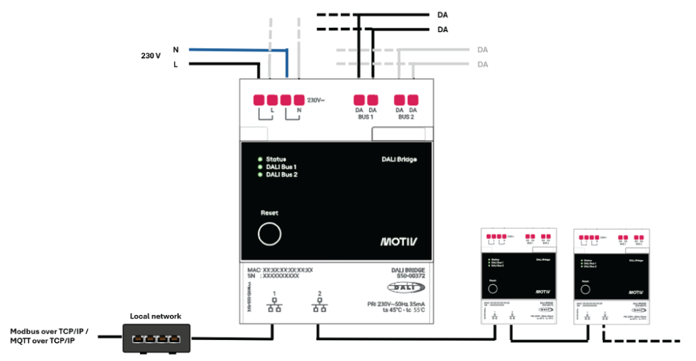
When installing multiple bridges, connect them through a network switch using Modbus LAN or by daisy-chaining the devices. Although the Modbus LAN can be shared with other IP-based systems, we recommend a dedicated Modbus network for the DALI bridges and the BM to ensure reliable operation.
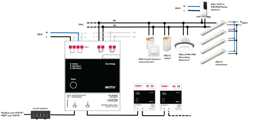
For the luminaires, the number of devices depends on the current consumption of each device. The total current consumption in one DALI line cannot exceed 200 mA (P48/M48) / 100 mA (P47) max., including a buffer of 20% for dynamic processes.
The Ethernet cable length between two connected devices must not exceed 100 m. For reliable network performance, it is recommended to limit a daisy-chain installation to a maximum of 10 DALI bridges.
Complete installation with basic wiring
Below is an example of a complete installation:
Single-phase power supply (recommended)
TIP: For optimum performance, power the entire DALI installation from a single electrical phase. This minimises electrical noise and reduces the risk of communication interference on the Modbus network.
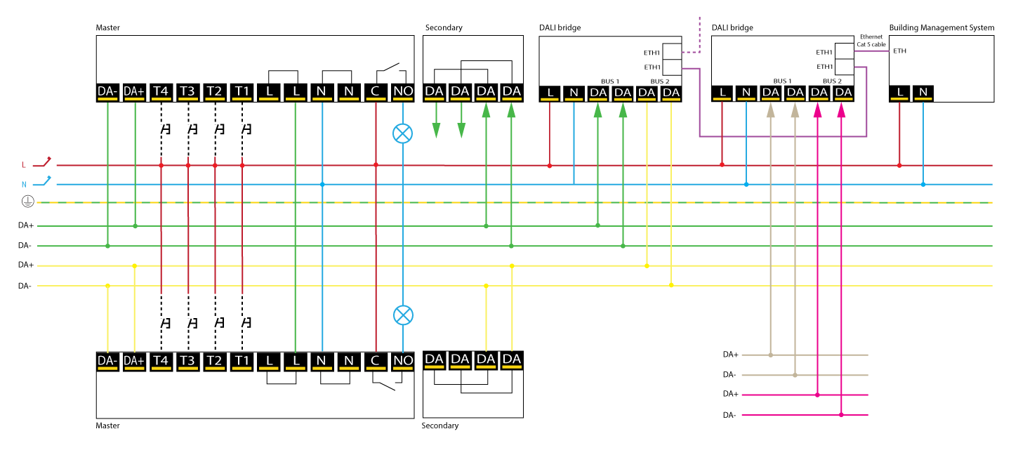
Multi-phase power supply
The DALI bridge supports multi-phase installations. The mains supply may be shared with equipment other than the lighting system.
Tip: We recommend avoiding sharing the same power cables with high-power equipment such as HVAC systems, industrial machinery, or elevators, as these may introduce electrical noise.
Note: The chance of communication interference increases in installations with multiple DALI bridges connected in a daisy chain, long cable runs, or multi-phase power distribution. To ensure reliable communication, follow recommended installation practices and minimise potential sources of electrical noise wherever possible.