The DALI bridge is designed for professional installation by qualified electricians only.
Requirements
The DALI bridge functions as a gateway between a DALI lighting management system and a network-based Building Management System (BMS).
Before connecting the DALI bridge to the DALI bus, ensure that the DALI lighting system, including the P40/M40 master detectors and all associated peripherals, is installed and commissioned correctly.
Firmware requirements
Only DALI-2 devices can be managed. To communicate with the DALI bridge, P47 and P48/M48 master detectors must be running firmware version 2.39 or later.
Gear requirements
In addition, all DALI-2 compliant control gear and luminaires must support:
-
IEC 62386-252 – Energy Data
-
IEC 62386-253 – Diagnostic Data
Network requirements
The DALI bridge connects to the building management system through a Modbus network.
Before starting the configuration, ensure that:
-
The DALI bridge is connected to the network
-
The PC or laptop used for configuration is connected to the same network and can communicate with the DALI bridge.
Cable requirements
The requirements are:
|
Requirement |
Description |
|---|---|
|
Wire capacity plug-in terminals |
cross section 1.5 - 2.5 mm² |
|
DALI-2 communication |
Two-wire, non-polarised bus, allowing either conductor to be connected to either DALI terminal |
Enclosure requirements
Electric shock hazard: The DALI bridge has unprotected electrical terminals. During operation, hazardous voltages may be present on the supply terminals.
Mounting requirements
The DALI bridge is designed for mounting on a DIN rail inside:
-
An electrical cabinet. (centralized installation)
-
A small box with a DIN rail that houses only the DALI bridge (decentralised installation); this box is typically installed very close to the detector.
Multiple DALI bridges can be installed.
Cabinet requirements
The cabinet or enclosure must provide adequate mechanical protection and allow sufficient ventilation for the installed devices to ensure that the devices can operate within their specified operation temperature and avoid overheating.
Cable requirements
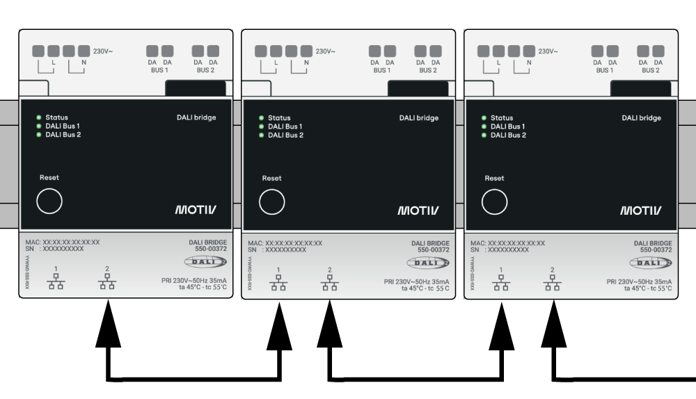
The Ethernet cable length between two connected devices must not exceed 100 m. For reliable network performance, we recommend limiting a daisy-chain installation to a maximum of 10 DALI bridges.
Mounting
Switch off the mains before installing.
Only qualified installers may install the DALi bride.
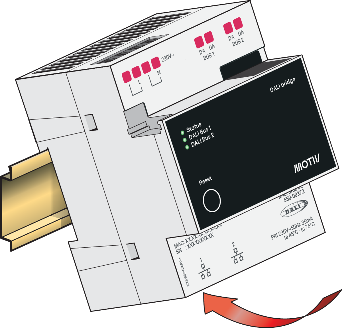
Step 1 - Fix the module
Click the module onto the DIN rail.
Step 2 - Connect the module
Connect the module according to the wiring diagram. For more information, go to DALI bridge wiring information
For information on how to configure the DALI bridge, go to Configuring the DALI bridge
When mounting multiple bridges, connect them in a daisy chain configuration.