
Overview
Location
The DALI bridge has three LEDs, located on the front panel:
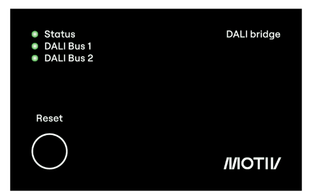
LED Overview
The table below provides an overview of the LED behaviour:
|
LED |
Colour |
State |
Description |
|---|---|---|---|
|
Status |

|
LED off |
No power connected |

|
Green: continuously on |
Power connected, module functioning correctly, no error |
|

|
Red: continuously on |
Any DALI bridge error |
|

|
Off |
Firmware installation in progress (see LED behaviour during firmware update) |
|

|
Green: flashing (0.5 s on, 0.5 s off) for 10 s |
Signal received from NHC to identify device |
|
|
DALI bus 1 or 2 |
|
Off |
No power connected to the DALI bridge |
|
|
Green: continuously on |
DALI bus OK, no overload |
|

|
Red: flashing (0.5 s on, 0.5 s off) |
No DALI bus connected, error on DALI bus, short circuit or over-current, or the P48/P47 detector cannot be found |
|
|
|
Green: flashing (0.5 s on, 0.5 s off) for 10 seconds |
Signal received to identify device (DALI bridge can be identified on the DALI buses). |
LED behaviour on power-up
On power-up:
-
All three LEDs light up red simultaneously for 0.5s
-
All three LEDs light up green for 0.5s,
-
All three LEDs turn off during 0.5s.
After that, the LEDs show the actual status.
LED behaviour during firmware update
The table below indicates the LED behaviour during a firmware update:
|
Step |
State |
LED behaviour |
|---|---|---|
|
1 |
Normal operation |
|
|
2 |
Firmware update started from the configuration interface. |
|
|
3 |
Firmware installation in progress |
|
|
4 |
Installation finished and DALI bridge restarts |
Refer to LED behaviour on power-up above |
|
5 |
Normal operation |
|
LED behaviour during factory reset
Refer to Perform a factory reset
Practical examples
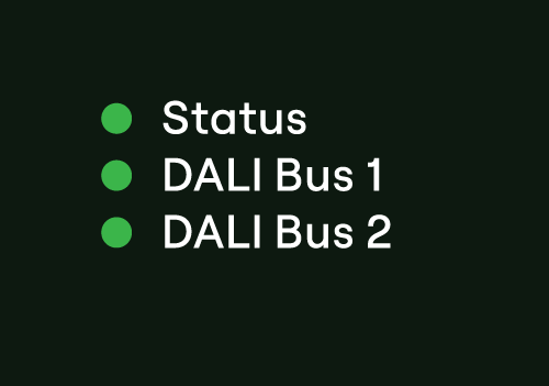
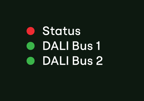
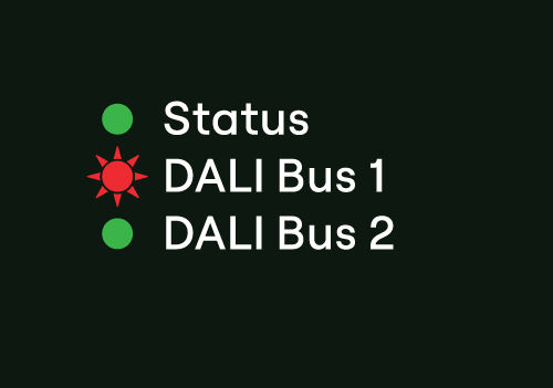
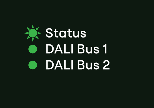
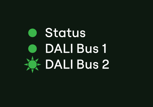
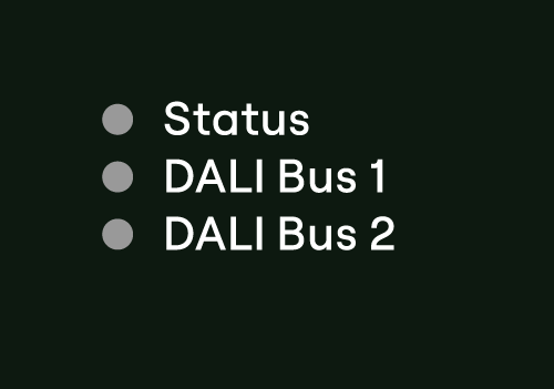
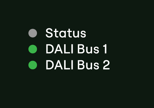
Below are some practical examples on how to interpret the Status (S) and DALI bus (D1, D2) LEDs:
|
LED Indication |
Description |
|---|---|
|
|
|
|
|
|
|
|
|
|
|
|
|
|